- Описание
- Характеристики
- Опубликовать комментарий
Трехполюсный контактор на 9 А, 4 кВт при 400 В с катушкой на 100–250 В AC/DC для управления трехфазными электродвигателями и силовыми цепями до 690 В AC и 440 В DC. Вспомогательная цепь 1×NO.
Ассортимент
| Rated operational | Rated control circuit voltage Uc min. … Uc max. |
Auxiliary contacts fitted |
Type | |||
| power 400 V AC-3 |
current θ ≤ 40 °C AC-1 |
|||||
| кВт | А | V 50/60 Hz | V DC | NO | NC | |
| 4 | 25 | 100...250 | 100...250 | 1 | 0 | AF09-30-10-13 |
(1) AF..-30-..-11 not suitable for direct control by PLC-output.
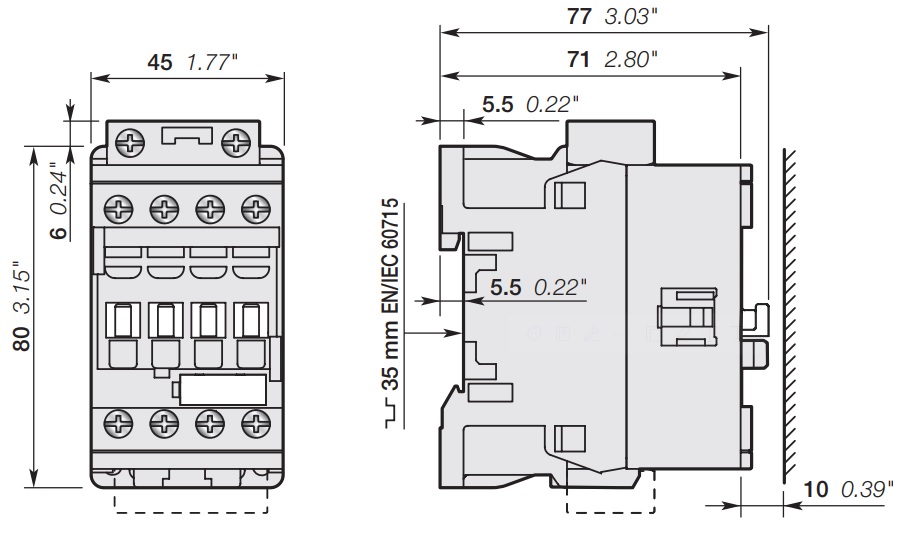
Основные размеры мм, дюймы
Technical data
| Тип контакторов | AC / DC operated | AF09 |
| Стандарты | МЭК 60947-1, МЭК 60947-4-1 | |
| Номинальное рабочее напряжение Ue max. | 690 В | |
| Номинальная частота (without derating) | 50 / 60 Гц | |
| Условный тепловой ток в открытом исполнении Ith, θ ≤ 40 °C | 35 A | |
| With conductor cross-sectional area | 6 mm² | |
| AC-1 Utilization category For air temperature close to contactor |
||
| Номинальный рабочий ток Ie, категория применения AC-1, температура окр. воздуха, Ue max. ≤ 690 V, 50/60 Hz |
θ ≤ 40 °C | 25 A |
| θ ≤ 60 °C | 25 A | |
| θ ≤ 70 °C | 22 A | |
| With conductor cross-sectional area | 4 mm² | |
| AC-3, AC-3e Utilization category For air temperature close to contactor θ ≤ 60 °C |
||
| Номинальный рабочий ток Ie, категория применения AC-3 / AC-3e, температура окр. воздуха θ ≤ 60 °C (1), 3-phase motors |
220-230-240 V | 9 А |
| 380-400 V | 9 А | |
| 415 V | 9 А | |
| 440 V | 9 А | |
| 500 V | 9,5 А | |
| 690 V | 7 А | |
| Номинальная рабочая мощность Pe, Категория применения AC-3 / AC-3e (1) 1500 r.p.m. 50 Hz 1800 r.p.m. 60 Hz 3-phase motors |
220-230-240 V | 2,2 кВт |
| 380-480 V | 4 кВт | |
| 415 V | 4 кВт | |
| 440 V | 4 кВт | |
| 500 V | 5,5 кВт | |
| 690 V | 5,5 кВт | |
| Номинальная включающая способность AC-3, AC-3e | 10 x Ie AC-3, 12 x Ie AC-3e acc. to IEC 60947-4-1 | |
| Номинальная отключающая способность AC-3, AC-3e | 8 x Ie AC-3, 8.5 x Ie AC-3e acc. to IEC 60947-4-1 | |
| AC-8a Utilization category (without thermal overload relay - Ue 400 V 50/60 Hz - θ ≤ 40 °C) |
||
| Номинальный рабочий ток Ie, категория применения AC-8a, without thermal overload relay - Ue 400 V 50/60 Hz - θ ≤ 40 °C |
12 A | |
| Номинальная рабочая мощность Pe, категория применения AC-8a |
5.5 kW | |
| Short-circuit protection device for contactors without thermal overload relay - Motor protection excluded (2) Ue ≤ 500 V AC - gG type fuse |
25 A | |
| Rated short-time withstand current Icw at 40 °C ambient temperature, in free air from a cold state |
1 s | 300 A |
| 10 s | 150 A | |
| 30 s | 80 A | |
| 1 min | 60 A | |
| 15 min | 35 A | |
| Maximum breaking capacity cos φ = 0.45 |
at 440 V | 250 A |
| at 690 V | 106 A | |
| Power dissipation per pole | Ie / AC-1 | |
| Ie / AC-3, AC-3e | ||
| Max. electrical switching frequency | AC-1 | 600 cycles/h |
| AC-3, AC-3e | 1200 cycles/h | |
| AC-2, AC-4 | 300 cycles/h | |
(1) For the corresponding kW/A or hp/A values of 1500 r.p.m, 50 Hz or 1800 r.p.m, 60 Hz, 3-phase motors, see "Motor rated operational powers and currents".
(2) For the protection of motor starters against short circuits, see "Coordination with short-circuit protection devices".
| Contactor types | AC / DC operated | AF09 |
| Номинальное напряжение по изоляции Ui | 690 V | |
| Номинальное импульсное выдерживаемое напряжение Uimp | 6 kV | |
| Electromagnetic compatibility | Devices complying with IEC/EN 60947-1 - Environment A and B (1) | |
| Pollution degree | 3 | |
| Ambient air temperature close to contactor | ||
| Operation | Fitted with thermal overload relay | -25...+60 °C |
| Without thermal overload relay | -40...+70 °C | |
| Storage | -60...+80 °C | |
| Climatic withstand | Category B according to IEC 60947-1 Annex Q | |
| Maximum operating altitude (without derating) | 3000 m | |
| Mechanical durability | Number of operating cycles | 10 millions operating cycles |
| Max. switching frequency | 3600 cycles/h | |
| Shock withstand acc. to IEC/EN 60068-2-27 |
||
| Mounting position 1 | Shock direction | 1/2 sinusoidal shock for 11 ms: no change in contact position, closed or open position |
| PICTURE 2 | A | |
| B1 | ||
| B2 | ||
| C1 | ||
| C2 | ||
| Vibration withstand 5...300 Hz acc. to IEC 60068-2-6 |
5...300 Hz 4 g closed position / 2 g open position |
|
(1) Environment B: all AF09...AF38 produced since week 08.2013.
AF09...AF38-..-..-12 (48 ...130 V 50 / 60 Hz - DC) compliant to environment A only: for environment B, select AF09...AF38Z-..-..-22.
| Contactor types | AC / DC operated | AF09 |
| Mounting positions | (PICTURE 3) | |
| Max. N.C. built-in and add-on N.C. auxiliary contacts: see accessory fitting details for a 3-pole contactor AF09 ... AF38 |
||
| Mounting distances | The contactors can be assembled side by side | |
| Fixing | On rail according to IEC/EN 60715 | 35 x 7.5 mm or 35 x 15 mm |
| By screws (not supplied) | 2 x M4 screws placed diagonally | |
| Contactor types | AC / DC operated | AF09 |
| Coil operating limits acc. to IEC 60947-4-1 |
AC supply | At θ ≤ 60 °C 0.85 x Uc min...1.1 x Uc max. At θ ≤ 70 °C 0.85 x Uc min...Uc max. |
| DC supply | At θ ≤ 60 °C 0.85 x Uc min...1.1 x Uc max. At θ ≤ 70 °C 0.85 x Uc min...Uc max. |
|
| AC control voltage 50/60 Hz | ||
| Rated control circuit voltage Uc | 24...500 V AC | |
| Coil consumption | Average pull-in value | 50 VA |
| Average holding value | 2.2 VA / 2 W | |
| DC control voltage | ||
| Rated control circuit voltage Uc | 20...500 V DC | |
| Coil consumption | Average pull-in value | 50 W |
| Average holding value | 2 W | |
| PLC-output control | Not suitable for direct control by PLC output | |
| Drop-out voltage | ≤ 60 % of Uc min. | |
| Voltage sag immunity acc. to SEMI F47-0706 |
- | |
| Dips withstand -20 °C ≤ θ ≤ +60 °C |
- | |
| Operating time | ||
| Between coil energization and: | N.O. contact closing | 40...95 ms |
| N.C. contact opening | 38...90 ms | |
| Between coil de-energization and: | N.O. contact opening | 11...95 ms |
| N.C. contact closing | 13...98 ms | |
| Contactor types | AC / DC operated | AF09 |
| Main terminals | Screw terminals with cable clamp | |
| Connection capacity (min. ... max.) Main conductors (poles) |
||
| Rigid Solid (≤ 4 mm²) Stranded (≥ 1 mm²) |
1 x | 1...6 mm² |
| 2 x | 1...6 mm² | |
| Flexible with non insulated ferrule | 1 x | 0.75...6 mm² |
| 2 x | 0.75...6 mm² | |
| Flexible with insulated ferrule | 1 x | 0.75...4 mm² |
| 2 x | 0.75...2.5 mm² | |
| Bars or lugs | L | 9.6 mm |
| Connection capacity acc. to UL/CSA | 1 or 2 x | AWG 16...10 |
| Stripping length | 10 mm | |
| Tightening torque | 1.5 Nm / 13 lb.in | |
| Auxiliary conductors (built-in auxiliary terminals + coil terminals) |
||
| Rigid solid/stranded | 1 x | 1...2.5 mm² |
| 2 x | 1...2.5 mm² | |
| Flexible with non insulated ferrule | 1 x | 0.75...2.5 mm² |
| 2 x | 0.75...2.5 mm² | |
| Flexible with insulated ferrule | 1 x | 0.75...2.5 mm² |
| 2 x | 0.75...1.5 mm² | |
| Lugs | L | 8 mm |
| Connection capacity acc. to UL/CSA | 1 or 2 x | AWG 18...14 |
| Stripping length | 10 mm | |
| Tightening torque | Coil terminals | 1.2 Nm / 11 lb.in |
| Built-in auxiliary terminals | 1.2 Nm / 11 lb.in | |
| Degree of protection acc. to IEC/EN 60947-1 and IEC/EN 60529 |
Main terminals | IP20 |
| Coil terminals | IP20 | |
| Built-in auxiliary terminals | IP20 | |
| Screw terminals | Delivered in open position, screws of unused terminals must be tightened | |
| Main terminals | M3.5 | |
| Screwdriver type | Flat Ø 5.5 / Pozidriv 2 | |
| Coil terminals | M3.5 | |
| Screwdriver type | Flat Ø 5.5 / Pozidriv 2 | |
| Built-in auxiliary terminals | M3.5 | |
| Screwdriver type | Flat Ø 5.5 / Pozidriv 2 | |
| Contactor types | AC / DC operated | AF09 |
| Rated operational voltage Ue max. | 690 V | |
| Rated frequency (without derating) | 50 / 60 Hz | |
| Conventional free air thermal current Ith - θ ≤ 40 °C | 16 A | |
| Ie / Rated operational current AC-15 acc. to IEC 60947-5-1 |
24-127 V 50/60 Hz | 6 A |
| 220-240 V 50/60 Hz | 4 A | |
| 400-440 V 50/60 Hz | 3 A | |
| 500 V 50/60 Hz | 2 A | |
| 690 V 50/60 Hz | 2 A | |
| Making capacity AC-15 | 10 x Ie AC-15 acc. to IEC 60947-5-1 | |
| Breaking capacity AC-15 | 10 x Ie AC-15 acc. to IEC 60947-5-1 | |
| Ie / Rated operational current DC-13 acc. to IEC 60947-5-1 |
24 V DC | 6 A / 144 W |
| 48 V DC | 2.8 A / 134 W | |
| 72 V DC | 1 A / 72 W | |
| 110 V DC | 0.55 A / 60 W | |
| 125 V DC | 0.55 A / 69 W | |
| 220 V DC | 0.27 A / 60 W | |
| 250 V DC | 0.27 A / 68 W | |
| 400 V DC | 0.15 A / 60 W | |
| 500 V DC | 0.13 A / 65 W | |
| 600 V DC | 0.1 A / 60 W | |
| Short-circuit protection device gG type fuse | 10 A | |
| Conditional short-circuit current | 1 kA | |
| Rated short-time withstand current Icw | for 1.0 s | 100 A |
| for 0.1 s | 140 A | |
| Minimum switching capacity with failure rate acc. to IEC 60947-5-4 |
12 V / 3 mA | |
| 10^7 | ||
| Non-overlapping time between N.O. and N.C. contacts | ≥ 2 ms | |
| Power dissipation per pole at 6 A | 0.1 W | |
| Max. electrical switching frequency | AC-15 | 1200 cycles/h |
| DC-13 | 900 cycles/h | |
| Mechanically linked contacts acc. to annex L of IEC 60947-5-1 |
Built-in N.O. or N.C. auxiliary contacts and additional N.O. or N.C. auxiliary contacts (CA4, CAL4, CAT4 aux. contact blocks) are mechanically linked contacts. |
|
| Mirror contacts acc. to annex F of IEC 60947-4-1 |
Built-in N.C. auxiliary contacts or additional N.C. auxiliary contacts (CA4, CAL4, CAT4 aux. contact blocks) are mirror contacts. |
|
| 3471523110038 | |
| 1SBL137001R1310 | |
| Трехполюсные контакторы AF |