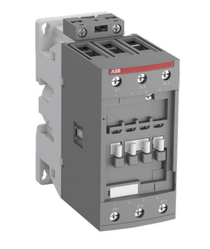
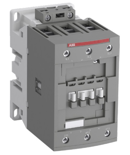
AF40 ... AF96 contactors are mainly used for controlling 3-phase motors and power circuits up to 1 000 V AC and 220 V DC. These contactors are of the block type design with 3 main poles.
- control circuit: AC or DC operated with electronic coil interface accepting a wide control voltage range (e.g. 100...250 V AC and DC), only 4 control voltage ranges covering 24...500 V 50/60 Hz and 20...500 V DC
- can manage large control voltage variations
- reduced panel energy consumption
- very distinct closing and opening.
- can withstand short voltage dips and voltage sags (SEMI F47-0706 conditions of use on request).
- built-in surge suppression
- add-on auxiliary contact blocks for front or side mounting and a wide range of accessories.
Ассортимент
| Rated operational | Rated control circuit voltage Uc min. … Uc max. |
Auxiliary contacts fitted |
Type | |||
| power | current θ ≤ 40 °C | |||||
| кВт | А | V 50/60 Hz | V DC | NO | NC | |
| 18.5 | 70 | 24...60 | 20...60 (1) | 0 | 0 | AF40-30-00-11 |
| 48...130 | 48...130 | 0 | 0 | AF40-30-00-12 | ||
| 100...250 | 100...250 | 0 | 0 | AF40-30-00-13 | ||
| 250...500 | 250...500 | 0 | 0 | AF40-30-00-14 | ||
| 22 | 100 | 24...60 | 20...60 (1) | 0 | 0 | AF52-30-00-11 |
| 48...130 | 48...130 | 0 | 0 | AF52-30-00-12 | ||
| 100...250 | 100...250 | 0 | 0 | AF52-30-00-13 | ||
| 250...500 | 250...500 | 0 | 0 | AF52-30-00-14 | ||
| 30 | 105 | 24...60 | 20...60 (1) | 0 | 0 | AF65-30-00-11 |
| 48...130 | 48...130 | 0 | 0 | AF65-30-00-12 | ||
| 100...250 | 100...250 | 0 | 0 | AF65-30-00-13 | ||
| 250...500 | 250...500 | 0 | 0 | AF65-30-00-14 | ||
| 37 | 125 | 24...60 | 20...60 (1) | 0 | 0 | AF80-30-00-11 |
| 48...130 | 48...130 | 0 | 0 | AF80-30-00-12 | ||
| 100...250 | 100...250 | 0 | 0 | AF80-30-00-13 | ||
| 250...500 | 250...500 | 0 | 0 | AF80-30-00-14 | ||
| 45/55 | 130 | 24...60 | 20...60 (1) | 0 | 0 | AF96-30-00-11 |
| 48...130 | 48...130 | 0 | 0 | AF96-30-00-12 | ||
| 100...250 | 100...250 | 0 | 0 | AF96-30-00-13 | ||
| 250...500 | 250...500 | 0 | 0 | AF96-30-00-14 | ||
(1) For control by PLC-output, use RA4 interface relay.
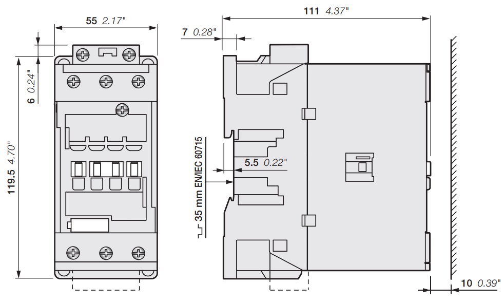
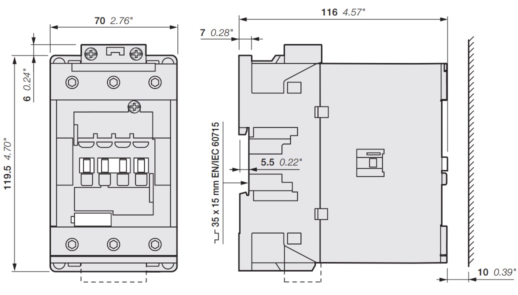
Main dimensions mm, inches
Technical data
| Contactor types | AC / DC operated | AF40 | AF52 | AF65 | AF80 | AF96 |
| Standards | IEC/EN 60947-1, IEC/EN 60947-4-1 | |||||
| Rated operational voltage Ue max. | 690 V | 1000 V | ||||
| Rated frequency (without derating) | 50 / 60 Hz | |||||
| Conventional free-air thermal current Ith acc. to IEC 60947-4-1, open contactors, θ ≤ 40 °C |
105 A | 105 A | 105 A | 130 A | 130 A | |
| With conductor cross-sectional area | 35 mm² | 35 mm² | 35 mm² | 50 mm² | 50 mm² | |
| AC-1 Utilization category For air temperature close to contactor |
||||||
| Ie / Rated operational current AC-1 Ue max. ≤ 690 V, 50/60 Hz |
θ ≤ 40 °C | 70 A | 100 A | 105 A | 125 A | 130 A |
| θ ≤ 60 °C | 60 A | 80 A | 90 A | 100 A | 105 A | |
| θ ≤ 70 °C | 50 A | 70 A | 80 A | 85 A | 90 A | |
| With conductor cross-sectional area | 25 mm² | 35 mm² | 35 mm² | 50 mm² | 50 mm² | |
| AC-3, AC-3e Utilization category For air temperature close to contactor θ ≤ 60 °C |
||||||
| Ie / Max. rated operational current AC-3, AC-3e (1) 3-phase motors |
220-230-240 V | 40 A | 53 A | 65 A | 80 A | 105 A |
| 380-400 V | 40 A | 53 A | 65 A | 80 A | 105 A | |
| 415 V | 40 A | 53 A | 65 A | 80 A | 96 A | |
| 440 V | 40 A | 53 A | 65 A | 80 A | 96 A | |
| 500 V | 35 A | 45 A | 55 A | 65 A | 80 A | |
| 690 V | 25 A | 35 A | 39 A | 49 A | 57 A | |
| 1000 V | - | - | - | 25 A | 30 A | |
| Rated operational power AC-3, AC-3e (1) 1500 r.p.m. 50 Hz 1800 r.p.m. 60 Hz 3-phase motors |
220-230-240 V | 11 kW | 15 kW | 18.5 kW | 22 kW | 30 kW |
| 380-480 V | 18.5 kW | 22 kW | 30 kW | 37 kW | 55 kW | |
| 415 V | 22 kW | 30 kW | 37 kW | 45 kW | 55 kW | |
| 440 V | 22 kW | 30 kW | 37 kW | 45 kW | 55 kW | |
| 500 V | 22 kW | 30 kW | 37 kW | 45 kW | 55 kW | |
| 690 V | 22 kW | 30 kW | 37 kW | 45 kW | 55 kW | |
| 1000 V | - | - | - | 35 kW | 40 kW | |
| Rated making capacity AC-3, AC-3e | 10 x Ie AC-3, 12 x Ie AC-3e acc. to IEC 60947-4-1 | |||||
| Rated breaking capacity AC-3, AC-3e | 8 x Ie AC-3, 8.5 x Ie AC-3e acc. to IEC 60947-4-1 | |||||
| AC-8a Utilization category (without thermal overload relay - Ue 400 V 50/60 Hz - θ ≤ 40 °C) |
||||||
| Ie / Rated operational current AC-8a | 53 A | 70 A | 85 A | 105 A | 120 A | |
| Rated operational power AC-8a | 25 kW | 37 kW | 45 kW | 55 kW | 65 kW | |
| Short-circuit protection device for contactors without thermal overload relay - Motor protection excluded (2) Ue ≤ 500 V AC - gG type fuse |
100 A | 125 A | 160 A | 160 A | 20 A | |
| Rated short-time withstand current Icw at 40 °C ambient temperature, in free air from a cold state |
1 s | 1000 A | 1000 A | 1000 A | 1200 A | 1200 A |
| 10 s | 600 A | 600 A | 600 A | 780 A | 780 A | |
| 30 s | 350 A | 350 A | 350 A | 450 A | 450 A | |
| 1 min | 250 A | 250 A | 250 A | 300 A | 300 A | |
| 15 min | 110 A | 110 A | 110 A | 140 A | 140 A | |
| Maximum breaking capacity cos φ = 0.45 |
at 440 V | 950 A | 950 A | 950 A | 1150 A | 1150 A |
| at 690 V | 600 A | 600 A | 600 A | 750 A | 750 A | |
| Power dissipation per pole | Ie / AC-1 | 3 W | 6.3 W | 7 W | 7.6 W | 8.2 W |
| Ie / AC-3, AC-3e | 1 W | 1.7 W | 2.7 W | 3 W | 4.5 W | |
| Max. electrical switching frequency | AC-1 | 600 cycles/h | ||||
| AC-3, AC-3e | 1200 cycles/h | |||||
| AC-2, AC-4 | 150 cycles/h | |||||
(1) For the corresponding kW/A or hp/A values of 1500 r.p.m, 50 Hz or 1800 r.p.m, 60 Hz, 3-phase motors, see "Motor rated operational powers and currents".
(2) For the protection of motor starters against short circuits, see "Coordination with short-circuit protection devices".
| Contactor types | AC / DC operated | AF40 | AF52 | AF65 | AF90 | AF96 |
| Rated insulation voltage Ui acc. to IEC 60947-4-1 |
690 V | 1000 V | ||||
| Rated impulse withstand voltage Uimp. | 6 kV | 8 kV | ||||
| Electromagnetic compatibility | Devices complying with IEC/EN 60947-1 - Environment A and B | |||||
| Pollution degree | 3 | |||||
| Ambient air temperature close to contactor | ||||||
| Operation | Fitted with thermal overload relay | -45...+70 °C | ||||
| Without thermal overload relay | -40...+70 °C | |||||
| Storage | -60...+80 °C | |||||
| Climatic withstand | Category B according to IEC 60947-1 Annex Q | |||||
| Maximum operating altitude (without derating) | 3000 m | |||||
| Mechanical durability | Number of operating cycles | 10 millions operating cycles | ||||
| Max. switching frequency | 3600 cycles/h | |||||
| Shock withstand acc. to IEC/EN 60068-2-27 Mounting position 1 |
||||||
| Shock direction | 1/2 sinusoidal shock for 11 ms: no change in contact position, closed or open position | |||||
| PICTURE 2 | A | 25 g | ||||
| B1 | 25 g closed position / 5 g open position | |||||
| B2 | 15 g | |||||
| C1 | 25 g | |||||
| C2 | 25 g | |||||
| Vibration withstand acc. to IEC 60068-2-6 | 5...300 Hz 3 g closed position / 3 g open position |
|||||
| Contactor types | AC / DC operated | AF40 | AF52 | AF65 | AF80 | AF96 |
| Coil operating limits acc. to IEC 60947-4-1 |
AC supply | At θ ≤ 70 °C 0.85 x Uc min...1.1 x Uc max. | ||||
| DC supply | At θ ≤ 70 °C 0.85 x Uc min...1.1 x Uc max. | |||||
| Rated control circuit voltage Uc / AC control voltage 50/60 Hz | 24...500 V AC | |||||
| Coil consumption | Average pull-in value | 25 VA | 40 VA | |||
| Average holding value | 4 VA / 2 W | |||||
| Rated control circuit voltage Uc / DC control voltage | 20...500 V DC | |||||
| Coil consumption | Average pull-in value | 25 W | 40 W | |||
| Average holding value | 2 W | |||||
| PLC-output control | Not suitable for direct control by PLC output | |||||
| Drop-out voltage | ≤ 60 % of Uc min. | |||||
| Voltage sag immunity acc. to SEMI F47-0706 | conditions of use on request | |||||
| Dips withstand -20 °C ≤ θ ≤ +60 °C |
20 ms average | |||||
| Operating time | ||||||
| Between coil energization and: | N.O. contact closing | 42...100 ms | ||||
| N.C. contact opening | 38...95 ms | |||||
| Between coil de-energization and: | N.O. contact opening | 17...100 ms | ||||
| N.C. contact closing | 19...105 ms | |||||
| Contactor types | AC / DC operated | AF40 | AF52 | AF65 | AF80 | AF96 |
| Mounting positions | (PICTURE 3) | |||||
| Max. N.C. built-in and add-on N.C. auxiliary contacts: see accessory fitting details for a 3-pole contactor AF40 ... AF96 |
||||||
| Mounting distances | The contactors can be assembled side by side | |||||
| Fixing | On rail according to IEC/EN 60715 | 35 x 7.5 mm or 35 x 15 mm | 35 x 15 mm | |||
| By screws (not supplied) | 2 x M4 or 2 x M6 screws placed diagonally | |||||
| Contactor types | AC / DC operated | AF40 | AF52 | AF65 | AF80 | AF96 |
| Main terminals | Screw terminals with double connector 2 x (9.3 width x 7.9/10.3 depth) |
Screw terminals with double connector 2 x (12.4 width x 9.3/11.1 depth) |
||||
| Connection capacity (min. ... max.) Main conductors (poles) |
||||||
| Rigid Stranded (≥ 6 mm²) |
1 x | 6...35 mm² | 6...70 mm² | |||
| 2 x | 6...35 mm² | 6...50 mm² | ||||
| Flexible with non insulated ferrule | 1 x | 4...35 mm² | 6...50 mm² | |||
| 2 x | 4...35 mm² | 6...50 mm² | ||||
| Flexible with insulated ferrule | 1 x | 4...35 mm² | 6...50 mm² | |||
| 2 x | 4...35 mm² | 6...50 mm² | ||||
| Bars or lugs | L < | 9.2 mm | 12.2 mm | |||
| Connection capacity acc. to UL/CSA | 1 or 2 x | AWG 10...2 | AWG 6...1 | |||
| Stripping length | 16 mm | 17 mm | ||||
| Tightening torque | 4 Nm / 35 lb.in | 6 Nm / 53 lb.in | ||||
| Auxiliary conductors (built-in auxiliary terminals + coil terminals) |
||||||
| Rigid solid/stranded | 1 x | 1...2.5 mm² | ||||
| 2 x | 1...2.5 mm² | |||||
| Flexible with non insulated ferrule | 1 x | 0.75...2.5 mm² | ||||
| 2 x | 0.75...2.5 mm² | |||||
| Flexible with insulated ferrule | 1 x | 0.75...2.5 mm² | ||||
| 2 x | 0.75...1.5 mm² | |||||
| Lugs | L < | 8 mm | ||||
| Connection capacity acc. to UL/CSA | 1 or 2 x | AWG 18...14 | ||||
| Stripping length | 10 mm | |||||
| Tightening torque | Coil terminals | 1.2 Nm / 11 lb.in | ||||
| Built-in auxiliary terminals | 1.2 Nm / 11 lb.in | |||||
| Degree of protection acc. to IEC/EN 60947-1 and IEC/EN 60529 |
Main terminals | IP10 (For IP20 degree of protection, use LT terminal shroud accessory) | ||||
| Coil terminals | IP20 | |||||
| Built-in auxiliary terminals | IP20 | |||||
| Screw terminals | Delivered in open position, screws of unused terminals must be tightened | |||||
| Main terminals | M6 | M8 | ||||
| Screwdriver type | Flat Ø 6.5 / Pozidriv 2 | Hexagon socket (s=4 mm) | ||||
| Coil terminals | M3.5 | |||||
| Screwdriver type | Flat Ø 5.5 / Pozidriv 2 | |||||
| Built-in auxiliary terminals | M3.5 | |||||
| Screwdriver type | Flat Ø 5.5 / Pozidriv 2 | |||||
| Contactor types | AC / DC operated | AF40 | AF52 | AF65 | AF80 | AF96 |
| Rated operational voltage Ue max. | 690 V | |||||
| Rated frequency (without derating) | 50 / 60 Hz | |||||
| Conventional free air thermal current Ith - θ ≤ 40 °C | 16 A | |||||
| Ie / Rated operational current AC-15 acc. to IEC 60947-5-1 |
24-127 V 50/60 Hz | 6 A | ||||
| 220-240 V 50/60 Hz | 4 A | |||||
| 400-440 V 50/60 Hz | 3 A | |||||
| 500 V 50/60 Hz | 2 A | |||||
| 690 V 50/60 Hz | 2 A | |||||
| Making capacity AC-15 | 10 x Ie AC-15 acc. to IEC 60947-5-1 | |||||
| Breaking capacity AC-15 | 10 x Ie AC-15 acc. to IEC 60947-5-1 | |||||
| Ie / Rated operational current DC-13 acc. to IEC 60947-5-1 |
24 V DC | 6 A / 144 W | ||||
| 48 V DC | 2.8 A / 134 W | |||||
| 72 V DC | 1 A / 72 W | |||||
| 110 V DC | 0.55 A / 60 W | |||||
| 125 V DC | 0.55 A / 69 W | |||||
| 220 V DC | 0.27 A / 60 W | |||||
| 250 V DC | 0.27 A / 68 W | |||||
| 400 V DC | 0.15 A / 60 W | |||||
| 500 V DC | 0.13 A / 65 W | |||||
| 600 V DC | 0.1 A / 60 W | |||||
| Short-circuit protection device gG type fuse | 10 A | |||||
| Conditional short-circuit current | 1 kA | |||||
| Rated short-time withstand current Icw | for 1.0 s | 100 A | ||||
| for 0.1 s | 140 A | |||||
| Minimum switching capacity with failure rate acc. to IEC 60947-5-4 |
12 V / 3 mA | |||||
| 10^7 | ||||||
| Non-overlapping time between N.O. and N.C. contacts | ≥ 2 ms | |||||
| Power dissipation per pole at 6 A | 0.1 W | |||||
| Max. electrical switching frequency | AC-15 | 1200 cycles/h | ||||
| DC-13 | 900 cycles/h | |||||
| Mechanically linked contacts acc. to annex L of IEC 60947-5-1 |
Built-in N.O. or N.C. auxiliary contacts and additional N.O. or N.C. auxiliary contacts (CA4, CAL4, CAT4 aux. contact blocks) are mechanically linked contacts. |
|||||
| Mirror contacts acc. to annex F of IEC 60947-4-1 |
Built-in N.C. auxiliary contacts or additional N.C. auxiliary contacts (CA4, CAL4, CAT4 aux. contact blocks) are mirror contacts. |
|||||