Ультразвуковые передатчики
EasyTREK и EchoTREK
Здесь передатчик в английском языке обозначает слово трансмиттер - transmitter, трансмиттер у нас обычно не говорят, а все слова заменяют на слово датчик, хотя в английском возможно есть некоторая разница. У нас обычно говорят либо уровнемер
Ультразвуковой датчик EasyTREK
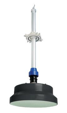
Ультразвуковой датчик EasyTREK
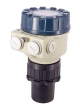
Ультразвуковой датчик уровня EchoTREK
Ультразвуковые устройства в повседневной жизни
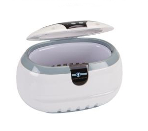
Ультразвуковой очиститель
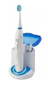
Ультразвуковая зубная щётка
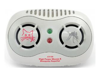
Ультразвуковой репеллент
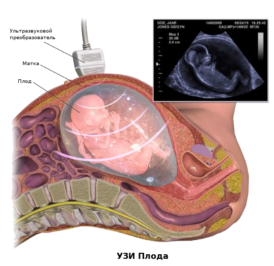
Ультразвуковые устройства в здравоохранении

Ультразвуковые „Устройства” в природе
Животные, такие как летучие мыши, используют ультразвук для обнаружения добычи и препятствий.

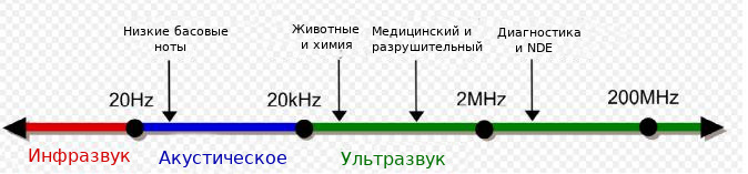
Ультразвук
Звуковые волны с частотами, превышающими верхний слышимый предел человеческого слуха, сходны со звуковым звуком по своим физическим свойствам.
Ультразвуковые устройства работают с частотами от 20 кГц до нескольких гигагерц
Человеческий слух
Диаграмма ультразвукового диапазона
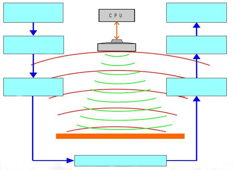
Принцип действия
Технология ультразвукового измерения уровня основана на принципе
- Измерения времени, необходимого для прохождения ультразвуковых импульсов от датчика к измеряемому уровню и обратно
Датчик испускает серию ультразвуковых импульсов и принимает отраженные эхо-сигналы
Интеллектуальное электронное устройство:
- Обрабатывает полученные сигналы
- Путем выбора эха, отраженного от поверхности, по времени полета вычисляет расстояние между датчиком и поверхностью.
Ультразвук
Теория расчета расстояния
C = s/t
Скорость ультразвука в сухом воздухе:
С = 343,8 м / с при 20 ° С
t = измеренное время полета
S = C/t
Расстояние = s/2
Скорость ультразвука
Скорость ультразвука зависит от:
- Среды, через которую проходит ультразвук (например, в воздухе скорость равна 343,8 м/с при 20 °C)
- Температуры (встроенная температурная компенсация)
ULTRASOUND
SOUND VELOCITY – TEMPERATURE

ULTRASONIC BEAM
A Total beam angle of 5°-7° at –3 dB
- Ensures a reliable measurement in narrow silos
- Unique focusing results deep penetration through:
gases, vapour and foam

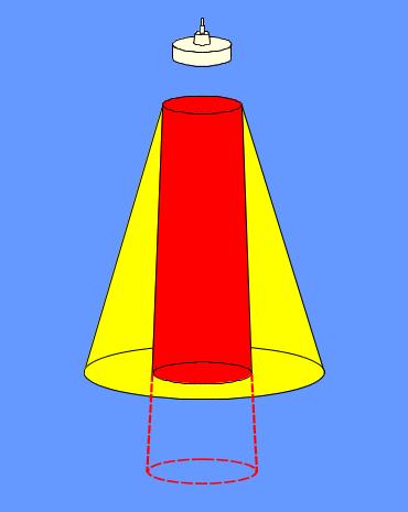
CONVENTIONAL 7-12°
NIVELCO5-7°
MEASURING RANGE
The range of a given sensor depends on:
- Power (high power = long range)
- Damping of the atmosphere during travelling (less concentration of particles in the air = less damping )
- Frequency Low frequency = high power = small damping (higher penetration)
- Reflection capability of the target
- Surface absorption (foam, powder)
- Surface scattering (granular)

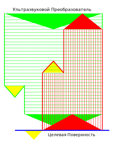
ULTRASOUND POWER
- Power of emitted ultrasonic signal
- Power-loss due to damping in the atmosphere
- Power of ultrasonic signal reaching the target surface
- Power-loss due to surface absorption
- Power of reflected ultrasonic signal
- Power-loss due to damping in the atmosphere
- Power of ultrasonic signal returning to sensor
ULTRASOUND POWER
Cause of signal damping: „2” and „6”
| LIQUIDS | SOLIDS |
|
|
Cause of signal damping: „ 4”
| LIQUIDS | SOLIDS |
|
|
DAMPING
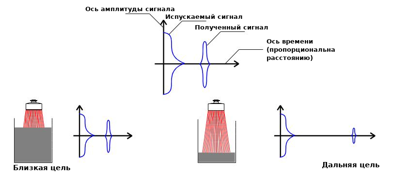
Signals reflected from closer targets are bigger,
in amplitude than the ones reflected from far targets.
DAMPING
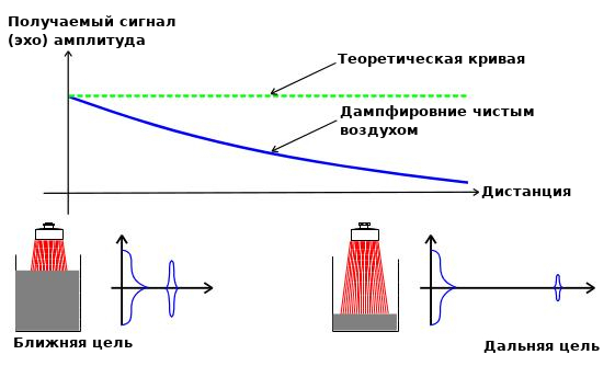
Air itself also has some damping effect on the ultrasonic signal.
DAMPING
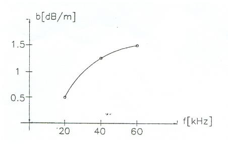
Damping depends on frequency
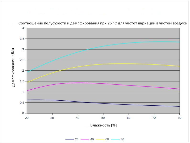
DAMPING
HUMIDITY FACTOR
DAMPING
TEMPERATURE FACTOR

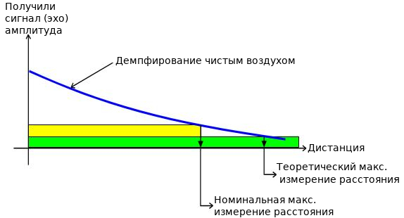
Signals falling into the „insensitive zone” can not be processed.
While specifying the measuring range a „safety zone” is also taken into account.
DAMPING
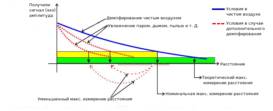
Measuring range will decrease due to increased damping.
MINIMUM MEASURING RANGE

The minimum measuring range is defined by the physical features of the transducer.
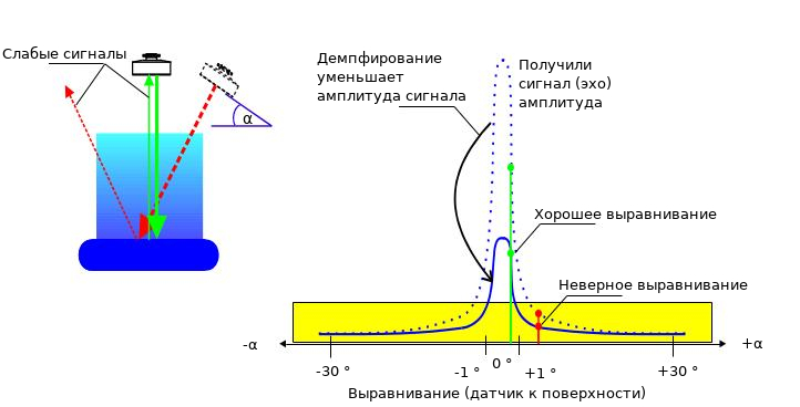
SENSOR ALIGNMENT
LIQUID APPLICATIONS
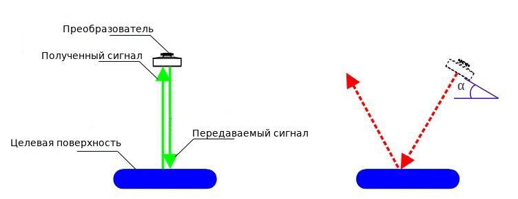
A smooth surface like that of liquids reflects ultrasound like a mirror.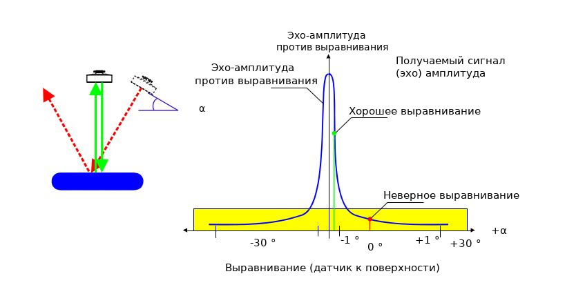
The received signal (echo) amplitude is very sensitive to alignment.
The received signal (echo) will not be detected in case of incorrect alignment.
SENSOR ALIGNMENT
LIQUID APPLICATIONS
The received signal (echo) will not be sensed in case of incorrect alignment.
AIMING IN SOLID APPLICATIONS

Surface of solids will scatter and absorb the ultrasound.
AIMING IN SOLID APPLICATIONS

Dust will damp the ultrasound. Echo will not be sensed in case of “incorrect” aiming.
AIMING IN SOLID APPLICATIONS
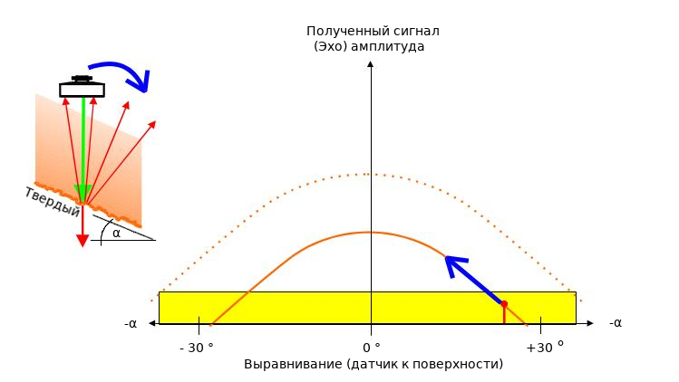
Sensor must be aimed in order to obtain the biggest possible signals.
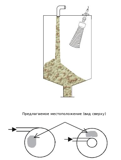
TRANSMITTER LOCATION, AIMING WAY OF FILLING
Gravity Filling
Select a location that
is as far away from
the filling point(s)
as possible.
Pneumatic Filling
Select a location
where the speed
of the in-flowing
material is the smallest.
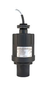
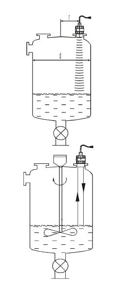
TRANSMITTER LOCATION OTHER CONSIDERATIONS
Optimal position:
- r = (0.2 to 0.4) d
- To avoid unwanted interferences caused by dome-top
- Sensor’s face has to be parallel to the surface of the medium
Protruding objects:
- No object should protrude into the ultrasonic beam of the device
Foam:
- Foam on the surface of the liquid can make ultrasonic measurement difficult or impossible
TRANSMITTER LOCATION OTHER CONSIDERATIONS
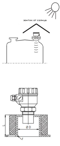
Sunshade:
- The transmitter should be protected against overheating (e.g. by direct sunshine) to avoid inaccurate measurement
Stand-off pipe:
- Rigid
- Inner rim* rounded * where the ultrasonic beam leaves the pipe
- Diameter and height as specified by NIVELCO