USAGE
Subsequent to powering the correctly wired device would start to tick and after 10 – 20 s ECHO LED go on and 4 – 20 mA signal appears on the current output. Measurement will be according to the factory setting. The factory setting is throughout apt to check proper working and to perform simple measurement tasks but features residing in the unit can only be utilised by adjusting the EasyTREK to the application by programming. For sound knowledge of the operation features and proper solving of difficult measurement applications the parts of the programming should carefully be studied.
LED indication:
- ECHO-LED
– On, if the unit detects proper echo
- COM-LED
– Blinking on HART communication
– Is ON in the state of remote programming
- RELAY-LED (optional)
– Lits, if CC-C2 is ON
– Does not lit, if CC-C1 is ON
Device can be reset to factory setting. Default of EasyTREK SP-500 is the following:
⇒ Measurement: level (LEV)
⇒ Zero level assigned to the maximum distance
⇒ Current output proportional to the level
⇒ 4 mA and 0% assigned to zero level.
⇒ 20 mA and 100% a assigned to the maximum level (minimum distance)
⇒ Error indication by the current output: holds last value.
⇒ Damping: 60 s.
View of the transmitter neck from above: 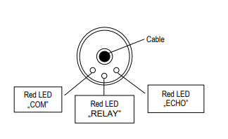
SPECIAL CONDITIONS OF SAFE USE
The cable outside the unit should be fixed so that it should be free of loading. The terminal box should be selected in accordance with the electrical class of the area.
PROGRAMMING
The HART interface of the EasyTREK provides for access to the whole parameter set and possibility of their programming. Parameter set can be reached in two different ways: by the use of the
– EView2 software run on the PC connected through HART modem to the loop or
– NIVELCO made MultiCONT multi-channel process control unit.
Since these access methods differ in their form and handling present manual does not review them. The information is contained in the relevant descriptions and user’s manuals.
MEASUREMENT CONFIGURATION
P00: - c b a Engineering Units
FACTORY DEFAULT: 000
Programming of this parameter will result in loading the factory default with the corresponding engineering units. Therefore all parameters should be set again!
| a | Operation |
| 0 | Liquid level measurement |
| b | Engineering units (according to “c”) | |
| Metric | US | |
| 0 | m | ft |
| 1 | cm | inch |
| c | Calculation system |
| 0 | metric |
| 1 | US |
P01: - - 1 a Measurement Mode
FACTORY DEFAULT: 11
Parameter value “a” will determine the basic measurement value that will be transmitted. Subsequently values for the relays are also relating to these quantities.
| a | Measurement mode | Transmitted value | Display symbol |
| 0 | Distance | Distance | DIST |
| 1 | Level | Level | LEV |
| 2 | Volume | Volume | VOL |
| 3* | Mass | Mass | MASS |
| 4 | Flow | Flow | FLOW |
* See: P32 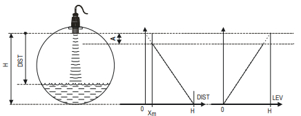
| Transmitted value | DIST | LEV=H-DIST |
| Parameters to set | P00 P01(a) = 0 P05 ≥ Xm |
P00 P01(a) = 1 P04 = H P05 ≥ Xm |
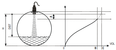
| Transmitted value | VOL fP40…P45(H-DIST) |
| Parameters to set | P00 P01(a) = 3 P02(b) P04 = H P05 ≥ Xm P40 … P45 |
A: Shortest measurable distance
B: Volume (content) pertaining to the greatest measurable level
C: Whole value of the vessel
D: diagram valid for the default value of P10 P11
P02: - c b a Calculation units
FACTORY DEFAULT: 000
| a | Temperature |
| 0 | °C |
| 1 | °F |
This table is interpreted according to P00(c), P01(a) and P02(c) and is irrelevant in case of percentage measurement [ P01(a)= 2 or 4 )]
| b | Volume | Weight (set also P32) | Volume flow | |||
| Metric | US | Metric | US | Metric | US | |
| 0 | m³ | ft³ | - | lb (pound) | m³/time | ft³/time |
| 1 | litre | gallon | tons | tonnes | litre/time | gallon/time |
| c | Time |
| 0 | s |
| 1 | min |
| 2 | hour |
| 3 | day |
Attention!
EasyTREK is a level transmitter. Although it can be used for measuring weight, due to factors involved in doing so, accuracy may essentially be influenced.
P03: - - - a Temperature compensation mode
FACTORY DEFAULT: 0
| a | Temperature compensation mode |
| 0 | Automatic |
| 1 | Manual |
Automatic: The compensation is done with using the value measured by the temperature sensor.
Manual: The compensation is done with a fixed setpoint temperature value independently of the measured value (P07).
Maximum Distance to be Measured (H)
FACTORY DEFAULT: XM as per chart
This is the only parameter that has to be programmed for each application other than distance (however to avoid disturbing effect of possible multiple echoes it is suggested to do this in distance measurement applications too).
The maximum distance to be measured is the greatest distance between the surface of the transducer and the farthest level to be measured. The factory programmed, greatest distances (DEFAULT values) which can be measured by the units are listed in the table below. For the actual application the maximum distance to be measured i.e. the distance between the sensor and the bottom of the tank should be entered in P04.
| EasyTREK Level transmitter for liquids | Maximum measuring distance XM[m (ft)] |
| Transducer material PP / PVDF | |
| SP-5A | 3 (10) |
| SP-59 | 5 (17) |
| SP-58 | 8 (26) |
| SP-57 | 10 (33) |
| SP-56 | 12 (40) |
| SP-54 | 18 (60) |
Since the level is determined by calculating the difference between the value set in P04 and distance (DIST) is measured by the unit, it is essential that the correct value of (H) is set in P04. To obtain the best accuracy it is suggested that this distance is measured in the empty tank.
P04 - - - - Maximum Distance to be Measured (H)
FACTORY DEFAULT: Xm as per chart
The range, beginning with the sensor’s surface, within which (due to the physical restraint of the ultrasound measurement system) measurement can not be made, is called the dead zone. The EasyTREK will not accept any echo within the blocking distance set here.
Close-end blocking may be represented as the extension of the dead zone within which a possible echo will not be taken into consideration making possible to exclude disturbing objects near to the sensor.
Automatic Close-end blocking = Dead Band control (P05 = Xm) Device with factory default will automatically set the smallest possible dead band depending on the conditions of the operation. This will be under optimal conditions a bit smaller in unfavourable circumstances greater than value given in the chart.
Manual Close-end-blocking with limitation ≥ dead zone (P05 > Xm) By entering a value, higher than the factory default the close-end blocking will be either the value programmed in P05 or the actual dead zone distance (influenced by the actual conditions of the application) whichever is greater.
| EasyTREK Level transmitter for liquids | Maximum measuring distance XMm (ft) |
| Transducer material PP / PVDF | |
| SP-5A | 3 (10) |
| SP-59 | 5 (17) |
| SP-58 | 8 (26) |
| SP-57 | 10 (33) |
| SP-56 | 12 (40) |
| SP-54 | 18 (60) |
Since the level is determined by calculating the difference between the value set in P04 and distance (DIST) is measured by the unit, it is essential that the correct value of (H) is set in P04. To obtain the best accuracy it is suggested that this distance is measured in the empty tank.
P05: - - - - Minimum measuring distance (Dead zone – Close-end blocking)
FACTORY DEFAULT: Xm as per chart
The range, beginning with the sensor’s surface, within which (due to the physical restraint of the ultrasound measurement system) measurement can not be made, is called the dead zone. The EasyTREK will not accept any echo within the blocking distance set here.
Close-end blocking may be represented as the extension of the dead zone within which a possible echo will not be taken into consideration making possible to exclude disturbing objects near to the sensor.
Automatic Close-end blocking = Dead Band control (P05 = Xm) Device with factory default will automatically set the smallest possible dead band depending on the conditions of the operation. This will be under optimal conditions a bit smaller in unfavourable circumstances greater than value given in the chart.
Manual Close-end-blocking with limitation ≥ dead zone (P05 > Xm) By entering a value, higher than the factory default the close-end blocking will be either the value programmed in P05 or the actual dead zone distance (influenced by the actual conditions of the application) whichever is greater.
| EasyTREK for liquids | Minimum measuring distance Xm m (in) |
| Sensor material PP / PVDF | |
| SP-5A | 0.15 (6) |
| SP-59 | 0.18 (7) |
| SP-58 | 0.2 (8) |
| SP-57 | 0.25 (10) |
| SP-56 | |
| SP-54 | 0.35 (12) |
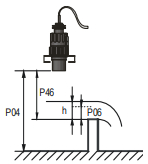
P06: - - - - Far-end blocking
FACTORY DEFAULT: 0
Far-end blocking is the range below the level set in parameter P06. The far-end blocking can be used to avoid disturbing effect of stirrer or heaters at the bottom of the tanks. Detecting echoes in this range the unit provides special signals.
A.) Measuring level or content
Level sinking below
- the value of P06 current output is according to the value of the far-end blocking and further
- below SUB 0 (7/8 of P06) the ERROR CODE 10 will be transmitted via HART
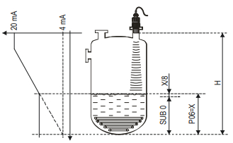
- Level rising over value of far-end blocking:
The calculation of level and volume will be based on the programmed tank dimensions, therefore the measured or calculated process values will not be influenced in any way, by the far end blocking value.
B.) Open channel flow metering
Far-end blocking will be used for those small levels below which the accurate volume flow calculation is no longer possible.
- Level in the flume/weir sinking below the blocked out range:
- Output current value will be according to the value of Q = 0
- 0 value transmitted via HART for display of „No Flow” or 0
- Level in the flume/weir rising over the blocked out range:
The calculation of volume flow will be based on the programmed flume/weir data; therefore the measurement values will not be influenced in any way, by the far end blocking value.
P07: - - - - Temperature compensation with fixed value
FACTORY DEFAULT: 20 ºC
Manual temperature compensation value
CURRENT OUTPUT
P08: - - - - Fixed current output
FACTORY DEFAULT: 0
P10: - - - - Value (of distance, level, volume or flow) assigned to 4 mA current output
FACTORY DEFAULT: 0
P11: - - - - Value (of distance, level, volume or flow) assigned to 20 mA current output
FACTORY DEFAULT: XM – Xm
Values are interpreted according to P01(a). Assignment can be made so that the proportion between the change of the (measured or calculated) process value and the change of the current output be either direct or inverse. E.g. level 1 m assigned to 4 mA and level 10 m assigned to 20 mA represents direct proportion and level 1 m assigned to 20 mA and level 10 m assigned to 4 mA represents the inverse proportion.
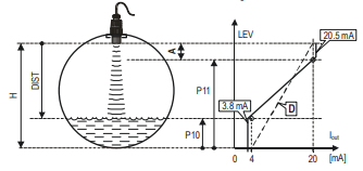
A: Smallest measurable dist.
D: diagram valid for default values of P10 and P11
P12: - - b a Current output mode
FACTORY DEFAULT: 0
Error indication by output current: Error will be indicated by the EasyTREK transmitter on the current output according to the set value as long as error is present.
(Error codes are given in Chapter 7).
| a | Error indication by output current |
| 0 | HOLD (hold last value) |
| 1 | 3.8 mA |
| 2 | 22 mA |
Current output mode:
| b | Current output mode |
| 0 | Automatic |
| 1 | Manual |
Automatic: The current output value is calculated from the measured value, the transmitter output is active.
Manual: The current output value is not calculated from the measured value, but a fixed (according to P08) current output value is transmitted.
In this mode, the current output error setting is irrelevant.
This parameter overwrites the HART multidrop communication mode 4 mA value!
RELAY OUTPUT
P13: - - - a Relay function
| a | Relay function | Also set: | |
| 0 | DIFFERENTIAL LEVEL CONTROL (Hysteresis control)Relay is energised if the measured or calculated value exceeds the value set in P14 Relay is de-energised if the measured or calculated value descends under the value set in P15 |
 |
P14, P15 There is a need to set (in level min. 20 mm) hysteresis between P14 and P15 P14 > P15 – normal operation P14 < P15 – inverted operation |
| 1 | Relay is energised in case of Echo Loss | - | |
| 2 | Relay is de-energised in case of Echo Loss | - | |
| 3 | COUNTER Used for open channel flow metering. A 100 msec pulse is generated every 1, 10, 100, 1.000 or 10.000 m3 according to P17. |
 |
P17 = 0: 1 m3 P17 = 1: 10 m3 P17 = 2: 100 m3 P17 = 3: 1.000 m3 P17 = 4: 10.000 m3 |
In de-energised state of the device the „C1” circuit is closed.
FACTORY DEFAULT: 2
P14: … Relay parameter – Operating value FACTORY DEFAULT: 0
P15: … Relay parameter – Releasing value FACTORY DEFAULT: 0
P17: … Relay parameter – Pulse rate FACTORY DEFAULT: 0
FACTORY DEFAULTS: P14=0, P15=0, P17=0
DIGITAL COMMUNICATION
P19: - - - a Short (HART) address of the unit
FACTORY DEFAULT: 2
These addresses with 0 – 63 are, in accordance with the HART standard, for distinguishing units in the same loop.
- Address: 0 current output of 4 – 20 mA operational
- Address: 1 – 15 current output is fixed to 4 mA.
MEASUREMENT OPTIMISATION
P20: - - - Damping
FACTORY DEFAULT: 60 SEC
Damping time is used to damp the unwanted fluctuations of the output and display. If the measured value changes rapidly the new value will settle with 1% accuracy after this set time. (damping according to an exponential function).
| For testing only | Applicable | |
| No or moderate fume / waves | 0 sec | 2 sec |
| Heavy or dense fume or turbulent waves | >6 sec | >10 sec |
P22: - - - a Dome top tank compensation
FACTORY DEFAULT: 0
This parameter can be used to reduce disturbing effect of possible multiple echoes
| a | Compensation | Remark |
| 0 | OFF | In case the EasyTREK is not mounted in the centre of the top and the top is flat. |
| 1 | ON | In case the EasyTREK is mounted in the centre of a tank with dome-shaped top |
P24: - - - a Target tracking speed
FACTORY DEFAULT: 0
In this parameter evaluation can be speed up at the expense of the accuracy.
| a | Tracking speed | Remark |
| 0 | Standard | For most applications |
| 1 | Fast | For fast changing level |
| 2 | Special | Only for special applications (measuring range is reduced to 50% of the nominal value) The measuring window is inactive and the EasyTREK will respond practically instantly to any target. |
P25: - - - a Selection of Echo within the measuring window
FACTORY DEFAULT: 0
A so-called measuring window is formed around the echo signal. The position of this measuring window determines the flight time for calculation of the distance to the target. (the picture below can be seen on the test oscilloscope) 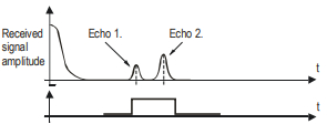
Some applications involve multiple (target + disturbing) echoes even within the measuring window. Basic echo selection will be done by the QUEST+ software automatically. This parameter influences the echo selection only within the measuring window.
| a | Echo in the window to be selected | Remark |
| 0 | With the highest amplitude | Most frequently used |
| 1 | First one | For liquids applications with multiple echoes within the Measuring Window |
P26: - - - - Level elevation rate (filling speed) (m/h or ft/h)
FACTORY DEFAULT: 2000 m/h
P27: - - - - Level descent rate (emptying speed) (m/h or ft/h)
FACTORY DEFAULT: 2000 m/h
These parameters provide additional protection against echo loss in applications involving very heavy fuming. Correct setting increases reliability of the measurement during filling and emptying. The parameters must not be smaller than the fastest possible filling/emptying rate of the actual technology.
Attention! Level changing rate is rather different near to the conical or spherical bottom of such a vessel.
P28 - - - a Echo loss indication
FACTORY DEFAULT: 0
| a | Echo loss indication | Remark |
| 0 | Delayed indication | During short echo-loss (for the period of 2(b+1)*P20) analogue output will hold last value. After this period the current value according to the setting in P12:a and via HART ERROR CODE 2 will be transmitted.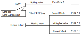 |
| 1 | No indication | For the time of echo-loss, analogue output will hold last value. |
| 2 | Filling simulation | Losing echo during the filling process, transmitted value will increase according to the filling speed set in P26 |
| 3 | Immediate indication | Losing echo, the current value (according to the setting in P12:a) and the ERROR CODE 2 (via HART) will immediately be transmitted. |
| 4 | Empty tank indication | Echo-loss may occur in completely empty tanks with a spherical bottom due to deflection of the ultrasonic beam, or in case of silos with an open outlet. In such cases it may be useful to indicate empty tank instead of echo loss. |
P29 - - - - Blocking out of disturbing object
FACTORY DEFAULT: 0
One fixed object in the tank, disturbing the measurement, can be blocked out. By the use of the Echo Map (P70) the precise distance of disturbing object can be read out. This value should be entered in this parameter.
P31: - - - - Sound velocity at 20 °C (m/s or ft/s depending on P00(c)
FACTORY DEFAULT :: 343.8 (m/s), 1128 (ft/s)
This parameter should be used if the sound velocity in the gases above the measured surface differs largely from that of in the air. This is recommended for applications where the gas is more or less homogeneous. If it is not, the accuracy of the measurement can be improved using 32-point linearisation (P48, P49).
For sound velocities in various gases see section “Sound Velocities”.
P32: - - - - Specific gravity
FACTORY DEFAULT: 0
Entering a value (other than “0”) of specific gravity in this parameter, the weight will be displayed instead of VOL.
Engineering unit should be [kg/dm3] or [lb/ft3] depending on P00 (c)
VOLUME (CONTENT) MEASUREMENT
P40: - - ba Tank shape
FACTORY DEFAULT: 00
| ba | Tank shape | Also to be set |
| b1 | Standing cylindrical tank shape (value of “b” as below) | P40 (b), P41 |
| 02 | Standing cylindrical tank with conical bottom | P41, P43, P44 |
| 02 | Standing rectangular tank (with chute) | P41, P42, P43, P44, P45 |
| b3 | Lying cylindrical tank shape (value of “b” as bellow) | P40 (b), P41, P42 |
| 04 | Spherical tank | P41 |
Attention!
The value “a” determining the
shape of the tank should be
set first.
P41-45: - - - - Tank dimensions
FACTORY DEFAULT: 0
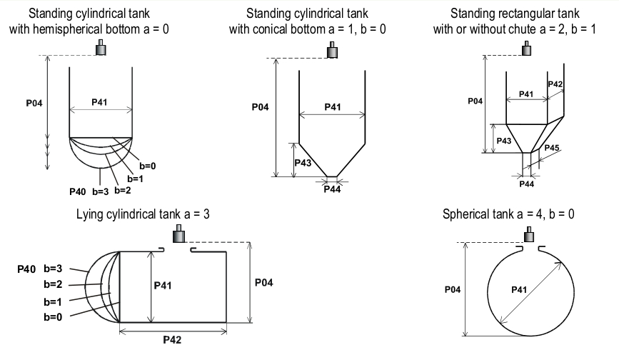
Plain bottom
P43, P44 and
P45 = 0
OPEN CHANNEL FLOW MEASUREMENT
P40: - - b a Devices, formula, data
FACTORY DEFAULT: 00
| ba | Devices, formula, data | Also to be set | |||||
| NIVELCO Parshall channels | Type | Formula | Qmin [l/s] | Qmax [l/s] | “P” [cm] | ||
| 00 | GPA-1P1 | 0.26 | 5.38 | 30 | P46 | ||
| 01 | GPA-1P2 | 0.52 | 13.3 | 34 | P46 | ||
| 02 | GPA-1P3 | 0.78 | 49 | 39 | P46 | ||
| 03 | GPA-1P4 | 1.52 | 164 | 53 | P46 | ||
| 04 | GPA-1P5 | 2.25 | 360 | 75 | P46 | ||
| 05 | GPA-1P6 | 2.91 | 570 | 120 | P46 | ||
| 06 | GPA-1P7 | 4.4 | 890 | 130 | P46 | ||
| 07 | GPA-1P8 | 5.8 | 1208 | 135 | P46 | ||
| 08 | GPA-1P9 | 8.7 | 1850 | 150 | P46 | ||
| 09 | General PARSHALL flume | P46, P42 | |||||
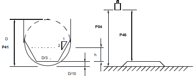
| 10 | PALMER-BOWLUS (D/2) | P46, P41 | |||||
| 11 | PALMER-BOWLUS (D/3) | P46, P41 | |||||
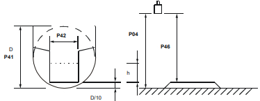
| 12 | PALMER-BOWLUS (Rectangular) | P46, P41, P42 | |||||
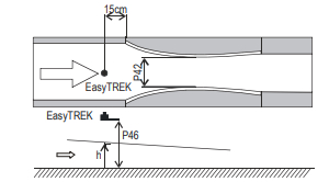
| 13 | Khafagi Venturi | P46, P42 | |||||
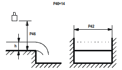
| 14 | Bottom-step weir | P46, P42 | |||||
| 15 | Suppressed rectangular or BAZIN weir | P46, P41, P42 | |||||
| 16 | Trapezoidal weir | P46, P41, P42 | |||||
| 17 | Special trapezoidal (4:1) weir | P46, P42 | |||||
| 18 | V-notch weir | P46, P42 | |||||
| 19 | THOMSON (90°-notch) weir | P46 | |||||
| 20 | Circular weir | P46, P41 | |||||
| 21 | General flow formula: Q [l/s] = 1000*P41*hP42, h [m] | P46, P41, P42 | |||||
P41-45: Flume / weir dimensions
FACTORY DEFAULT: 0
| P40=00 . . . |
NIVELCO Parshall flumes (GPA1P1 – GPA-1P9) For further details see the Manual of the Parshall flume |
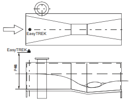 |
||||||||||||||
| P40=09 | General Parshall flume 0.305 < P42(width) < 2.44 Q [l/s]=372*P42*(h/0,305)1,569P420,026 2.5 < P42 Q [l/s] = K*P42*h1.6 P = 2/3*A
|
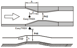 |
| P40=10 | Palmer-Bowlus (D/2) flume Q [m3/s] = f(h1/P41)*P412.5,where h1[m] = h+(P41/10) P41 [m] |
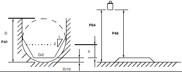 |
| P40=11 | Palmer-Bowlus (D/3) flume Q [m3/s] = f(h1/P41)*P412.5, where h1[m] = h+(P41/10) P41 [m] |
 |
| P40=12 | Palmer-Bowlus (rectangular) flume Q [m3/s] = C*P42*h1.5, where C= f(P41/P42) P41 [m], P42 [m] |
 |
| P40=13 | Khafagi Venturi flume Q [m3/s] = 1.744 *P42 * h1.5 + 0.091 * h2.5 P42 [m] h [m] |
 |
| P40=14 | Bottom step weir 0.0005 < Q [m3/s] < 1 0.3 < P42 [m] < 15 0.1 < h [m] < 10 Q [m3/s] = 5.073 * P42 * h1.5 Accuracy: ±10% |
 |
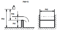
| P40=15 | Suppressed rectangular or BAZIN weir 0.001 < Q [m3/s] < 5 0.15 < P41 [m] < 0.8 0.15 < P42 [m] < 3 0.015 < h [m] < 0.8 Q [m3/s] = 1.77738(1+0.1378h/P41) * P42 * (h+0.0012)1.5 Accuracy: ±1% |
 |
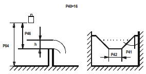
| P40=16 | Trapezoidal weir 0.0032 < Q [m3/s] < 82 20 < P41[°] < 100 0.5 < P42 [m] < 15 0.1 < h [m] < 2 Q [m3/s] = 1.772 * P42 * h1.5 + 1.320 *tg(P41/2) * h2.47 |
 |
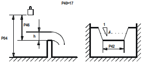
| P40=17 | Special trapezoidal (4:1) weir 0.0018 < Q [m3/s] < 50 0.3 < P42 [m] < 10 0.1 < h [m] < 2 Q [m3/s] = 1.866 * P42 * h1.5 Accuracy: ±3% |
 |
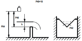
| P40=18 | V-notch weir 0.0002 < Q [m3/s] < 1 20 < P42[°] < 100 0.05 < h [m] < 1 Q [m3/s] = 1.320 * tg(P42/2) * h2.47 Accuracy: ±3% |
 |
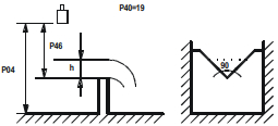
| P40=19 | THOMSON (90°-notch) weir 0.0002 < Q [m3/s] < 1 0.05 < h [m] < 1 Q [m3/s] = 1.320 * h2.47 Accuracy: ±3% |
 |
| P40=20 | Circular weir 0.0003 < Q [m3/s] < 25 0.02 < h [m] < 2 Q [m3/s] = m*b * D2.5. where b = f (h/D) m= 0.555+0.041 * h/P41+(P41/(0.11 * h)) Accuracy: ±5% |
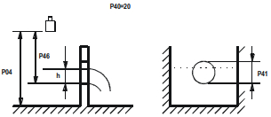 |
P46: - - - - Distance at Q = 0
FACTORY DEFAULT: 0
Distance between sensor surface and the level at which flow starts has to be entered in this parameter.
PROGRAMMING THE VOLUME / MASS / FLOW TABLE (VMFT)
P47: - - - a The operation of VMFT
FACTORY DEFAULT: 0
The customer can assign output signals in accordance with optional characteristics to values measured by the transmitter. The characteristic can be defined with maximum 32 points. Between the points the device will calculate the output signal from the measured value with linear interpolation. It can be used for example for assigning optional output signal to the measured value or calculating volume from level in case of tank shapes not included in the selection (e.g. tank with dent).
| a | VMFT mode |
| 0 | doesn’t work |
| 1 | works |
Conditions of correct programming of the data pairs
- The table must always start with L(1)= 0 and r(1)= output value (assigned to 0 level).
- The L column can not include identical values.
- If the table contains less than 32 data pairs, the L column must be ended with a level value ”0” in the row following the last relevant data pair.
| i | L (Left column) Level values measured | r (Right column) Output value |
| 1 | 0 | r(1) |
| 2 | L(2) | r(2) |
| L(i) | r(i) | |
| nn | L(nn) | r(nn) |
| nn+1 | 0 | |
| 32 |
P48: Number of VMFT elements
Shows the number of data pairs entered to VMFT. Read-only parameter.
INFORMATIONAL PARAMETERS (READ ONLY PARAMETERS)
P60: - - - - Overall operating hours of the unit (h)
P61: - - - - Time elapsed after last switch-on (h)
P62: - - - - Operating hours of the relay (h)
P63: - - - - Number of switching cycles of the relay
P64: - - - - Actual temperature of the transducer (°C / °F)
Broken loop of the thermometer will be indicated by display of the Pt Error message initiated by a signal sent via HART. In this case the transmitter will perform temperature correction corresponding to 20 ºC.
P65: - - - - Maximum temperature of the transducer (°C / °F)
P66: - - - - Minimum temperature of the transducer (°C / °F)
P70: - - - - Number of Echoes / Echo Map
Amplitude and position of the echoes can also be read out.
P71: - - - - Distance of the of Measuring Window
P72 - - - - Amplitude of the selected echo [dB] P73: Position of the selected echo (time) :(ms) [ms]
P74: Signal To Noise Ratio
| Ratio | Measurement conditions |
| Over 70 | Excellent |
| Between 70 and 30 | Good |
| Under 30 | Unreliable |
P75: - - - - Blocking Distance
The actual close-end blocking distance will be displayed (provided automatic blocking was selected in P05).
ADDITIONAL PARAMETERS OF THE FLOW METERING
P76: - - - - Head of flow (LEV) (Read only parameter)
The Headwater value can be checked here. This is the “h” value in the formula for flow calculation.
P77: - - - - TOT1 volume flow totalised (resettable)
P78: - - - - TOT2 volume flow totalised (non-resettable)
OTHER PARAMETERS
P96: - - - - Software code 1 (Read only parameter)
P97: - - - - Software code 2 (Read only parameter)
P98: - - - - Hardware code (Read only parameter)
P99: - - - - Access lock by secret code
The purpose of this feature is to provide protection against accidental programming or intentional reprogramming of parameters by a person not entitled to do so. The secret code can be any value other than 0000. Setting a secret code will automatically be activated when the EasyTREK is returned to the Measurement Mode. In order to program locked device the secret code should be entered first in P99. Thus for entering a new code or erasing the old one the knowledge of the previous code is necessary.